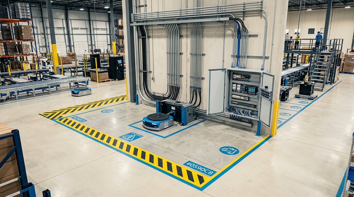
Robot fleet charging: Autonomous infrastructure
Charging infrastructure directly determines how large an AMR fleet needs to be and how available it stays in continuous operation. This guide breaks down charging-cycle planning, battery technologies, and redundancy concepts without committing to any one charging system.
In multi-shift industrial and service operations, energy management directly dictates the Overall Equipment Effectiveness (OEE) of an autonomous mobile robot (AMR) fleet. When charging cycles are managed purely reactively, directing vehicles to a centralized charging station only when their State of Charge (SoC) reaches a critical threshold, operational bottlenecks and unscheduled downtime are unavoidable. Modern 24/7 continuous operations rely instead on predictive opportunity charging (in-process charging), topping up the battery in short spurts whenever the vehicle is stationary at staging areas, workstations, loading and unloading points, or turnarounds.
Key Takeaways
- 1Opportunity charging in a narrow state-of-charge window can double the lifecycle of lithium cells compared to full discharges.
- 2Automated in-process charging eliminates manual battery swaps, potentially reducing the required fleet size by up to 32%.
- 3NMC cells provide 150-250 Wh/kg of energy density, while LFP cells prioritize thermal stability and higher cycle counts.
- 4Inductive charging reaches efficiencies comparable to good wired chargers and provides wear-free power transfer, ideal for sterile environments.
Charging cycle planning for AMR fleets in continuous operation
Battery degradation research demonstrates that cyclic stress on lithium-based cells depends heavily on the utilized SoC window. Cycle-life data for cobalt-based lithium-ion (NMC) cells shows roughly 600 discharge cycles at 60% depth of discharge against only about 300 cycles at full 100% depth of discharge, so halving the discharge depth roughly doubles the usable cycle count. Maintaining cells in a moderate charge state during micro-pauses protects the electrode structure and substantially extends operational lifespan. Furthermore, eliminating the energy-intensive upper SoC charging zone shortens charging durations significantly, as it bypasses the slow transition from constant current (CC) to constant voltage (CV) mode.
Dynamic C-rate control across the fleet network
Alongside the charge window, the charging rate (C-rate) plays a decisive role in long-term State of Health (SoH). While opportunity charging utilizes short bursts of higher current to recover operational range in minutes, unmanaged fast charging causes thermal stress and accelerated chemical aging. An adaptive fleet management system throttles power dynamically: if an AMR has a scheduled 20-minute dwell time in a staging buffer, the charge rate is reduced; if cycle schedules are compressed, the maximum permissible charging current is authorized. Intelligent C-rate management therefore extends usable battery lifespan while mitigating peak loads across the facility electrical grid.
- Trigger charging while 20% to 30% of capacity remains rather than allowing deep discharges that damage the cells.
- Cap the routine upper charge limit below a full charge: a lower peak charge voltage measurably increases the number of cycles a lithium cell delivers, and staying below the top of the window also bypasses lengthy constant-voltage charging phases.
- Dynamically modulate charging current based on real-time task queues and buffer dwell times.
- Continuously monitor cell temperatures to prevent localized thermal accumulation during high-current charging.
Fleet size calculation: Charging times vs. operating time
Dimensioning an autonomous mobile robot fleet requires a precise mathematical balance between net transport time, charging duration, and transit times to charging infrastructure. In traditional fleet setups relying on manual battery swaps or rigid centralized charging blocks, facility managers routinely provision 20% to 30% additional reserve vehicles simply to maintain baseline throughput. Automated in-process charging systems eliminate manual intervention entirely and synchronize energy replenishment directly with the material flow.
Transitioning to automated in-process charging stations noticeably reduces required fleet size because fewer redundant vehicles are needed on standby. Providers of inductive in-process charging technology report that an automated guided vehicle (AGV) or AMR fleet can be sized up to 32% smaller while delivering identical operational output. Sizing models calculate the required fleet volume by relating the total number of hourly transport missions to the cycle time adjusted for energy consumption:
- Calculate net travel time per transport cycle, including loaded travel, empty return runs, and handover times.
- Determine specific energy consumption per cycle based on vehicle payload, transit velocity, and floor inclines.
- Calculate the charging time factor based on available charging power, docking overhead, and transfer efficiency.
- Establish minimum fleet size by incorporating required availability buffers and infrastructure redundancy factors.
The three primary operational models present distinct trade-offs: Central block charging requires only a basic centralized charging room, but sacrifices vehicle availability and demands the largest fleet reserve. Manual battery swapping improves vehicle availability, but requires dedicated swap stations, spare battery inventories, and manual labor. Automated in-process charging provides the highest availability and largely eliminates reserve vehicles, while providers note that vehicle batteries can require up to 30% less capacity due to continuous top-ups.
Battery technologies compared: Li-ion vs. LFP
Selecting the optimal cell chemistry is a fundamental engineering decision with immediate consequences for payload capacity, vehicle chassis height, cycle life, and facility fire safety. Two main chemistries dominate autonomous industrial robotics: nickel manganese cobalt (NMC) lithium-ion cells and lithium iron phosphate (LFP) cells. Both support brief peak loads up to 3 C during acceleration and fast-charging phases, but their structural characteristics diverge significantly.
NMC cells offer a high gravimetric energy density of 150 to 250 Wh/kg. This energy density enables compact and lightweight battery enclosures, which is essential for low-profile under-ride tuggers, mobile manipulators, and high-speed sorting robots. However, NMC chemistry exhibits a thermal runaway onset temperature of approximately 210 degrees Celsius, necessitating rigorous multi-layer battery management systems (BMS) and reinforced enclosure packaging.
LFP cells have a lower energy density of 90 to 160 Wh/kg, but deliver superior thermal resilience and cycle stability. With a thermal runaway threshold of around 270 degrees Celsius and a chemical structure that does not release oxygen during cell breakdown, LFP cells are inherently resistant to self-sustaining fires. Furthermore, LFP cells typically achieve 3,000 to over 5,000 full cycles before dropping to 80% residual capacity, whereas standard NMC cells generally degrade after 800 to 1,500 full cycles.
| Characteristic | NMC (Nickel Manganese Cobalt) | LFP (Lithium Iron Phosphate) |
|---|---|---|
| Cell Energy Density | 150 - 250 Wh/kg | 90 - 160 Wh/kg |
| Cycle Life (to 80% Capacity) | 800 - 1,500 cycles | 3,000 - 5,000+ cycles |
| Thermal Runaway Threshold | approx. 210 °C | approx. 270 °C |
| Primary Application Focus | Compact chassis, mobile manipulators, low tare weight | Heavy-payload AMRs, 24/7 high-utilization fleets, demanding environments |
Autonomous docking and physical interfaces
Autonomous charging depends on reliable physical and electrical coupling between the mobile robot and the stationary power source. The two dominant physical interface paradigms deployed in industrial and commercial environments are physical contact systems and contactless inductive systems.
Contact-based charging relies on spring-loaded charging pins, floor-mounted plates, or side-mounted copper brushes. These systems deliver high charging currents at relatively low initial hardware costs. However, they require tight mechanical docking accuracy, typically within a few millimeters, and create mechanical wear over thousands of docking cycles. Friction generates copper dust, which can contaminate sensitive electronics and requires routine cleaning, while worn contacts risk sparking or incomplete circuit closure.
Inductive wireless charging transmits electrical power magnetically across an air gap between stationary and mobile coils. Systems available on the market achieve electrical transmission efficiencies of up to 93%, a level comparable to good wired chargers. Contactless systems eliminate exposed electrical conductors, mechanical wear, and conductive particle abrasion entirely, making inductive charging the preferred solution in cleanrooms, hospitality corridors, healthcare facilities, and wet or wash-down production areas.
- Contact systems: High power density and economical hardware, requiring regular mechanical inspection and cleaning.
- Inductive systems: Sealed, contactless power transfer with no sliding contacts to wear out and efficiency of up to 93%, comparable to the best wired chargers.
- Positioning tolerance: Inductive pads accommodate lateral positional offsets of several centimeters without interrupting energy transfer.
Redundancy in the charging infrastructure
Concentrating power supply in a single centralized charging area introduces a critical single point of failure into fleet operations. If a central distribution panel trips or a main circuit experiences a fault, an entire AMR fleet can be stranded within hours. Robust continuous operations instead distribute connection points across active facility sectors, since modern charging pads can be installed flexibly along travel paths, at buffer zones, and at loading and unloading stations rather than in one dedicated charging room.
Implementing an N+1 redundancy strategy ensures operational continuity. If a facility requires ten active charging points to balance fleet energy consumption during peak shifts, deploying eleven or twelve decentralized stations allows the fleet management system to dynamically re-route robots to adjacent stations whenever a single dock requires maintenance or encounters an electrical fault.
- Decentralized placement: Distribute charging stations across pick, drop, and staging zones to prevent transit congestion.
- N+1 capacity margin: Maintain at least one redundant charging dock per operational zone to absorb localized station outages.
- Dynamic traffic re-routing: Fleet dispatchers automatically divert robots to backup pads upon detecting station communication timeouts.
- Grid load balancing: Stagger charging authorizations across building phases to prevent concurrent peak demand surcharges.
Safety standards and regulatory requirements
Deploying autonomous charging stations in shared human-robot environments requires strict adherence to European and international safety frameworks. Stationary charging units and mobile platforms must comply with the harmonized safety requirements defined in ISO 13482, which specifies inherently safe design and protective measures for personal care robots, including mobile servant robots operating in commercial, healthcare, and hospitality facilities.
At the machinery level, installations must satisfy the safety, health, and risk-assessment mandates of the EU Machinery Regulation 2023/1230. Automated docking sequences must feature fail-safe zone monitoring, ensuring that high-voltage or high-current charging paths only energize once an authorized vehicle is positively identified and correctly positioned.
In addition to functional physical safety, connected charging infrastructure must incorporate industrial cybersecurity controls in line with IEC 62443. System architectures must strictly segregate safety-critical motion logic from encrypted fieldbus communications to prevent unauthorized network access or malicious command injection across connected charging endpoints.
From requirements specification to live fleet
Bridging the gap between an operational charging strategy and a live, production-grade deployment requires structured planning and verified systems integration. Operators begin by translating operational shift patterns, throughput volumes, and ambient facility conditions into concrete technical requirements. Software tools like the Spec Engine translate plain-language shift descriptions into formally verified, deployable action specifications within 48 hours, establishing the exact energy budgets and docking constraints required for continuous duty.
Once technical specifications are defined, OEM evaluation tools like Supplier Match evaluate and score over 44 robot manufacturers against regulatory readiness, integration footprint, and battery compatibility. Pre-built integration middleware such as Connectors links the robotic fleet directly to existing operational software stacks, including warehouse management systems (WMS), property management systems (PMS), and electronic health record (EHR) platforms.
During live multi-shift operation, werob provides unified oversight through its platform architecture. The centralized fleet management interface, Cockpit, tracks four operational dimensions across hardware health, charging infrastructure availability, regulatory compliance, and specification fidelity. Real-time telemetry surfaces early battery degradation, optimizes opportunity charging windows, and ensures that autonomous fleets maintain maximum availability across 24/7 continuous operations.
FAQ
- How does opportunity charging affect robot battery lifespan?
- Targeted opportunity charging -- keeping the fleet's batteries continuously within a 30 to 90 percent state-of-charge band -- reduces thermal and chemical stress. Compared to conventional deep charging, this approach can effectively double cell lifespan.
- Why is charging infrastructure critical to fleet size?
- Efficient, automated charging systems minimize downtime for every autonomous mobile robot (AMR). When vehicles don't need hours of manual charging, the need for redundant backup robots drops -- reducing the required total fleet size by up to 15 percent.
- What is the difference between LFP and conventional Li-ion batteries?
- Classic lithium-ion cells (such as NMC) offer high energy density of 150 to 250 Wh/kg, enabling compact designs. Lithium iron phosphate (LFP) cells offer less capacity per weight at 90 to 120 Wh/kg, but stand out for far greater thermal stability and longevity.
- What advantages does inductive charging offer over contact charging?
- Contact-based charging reaches electrical efficiency above 94 percent but is subject to mechanical wear. Inductive charging transfers energy wirelessly at roughly 85 to 90 percent efficiency. This prevents abrasion and sparking, making it ideal for dirty or wet production environments.
- How quickly can a robot battery be swapped?
- With modern automated battery-swap stations, a depleted battery can be exchanged for a fully charged unit in around 84 seconds. This eliminates regular charging time from the deployment schedule and ensures maximum fleet availability in 24/7 operation.
Related reading
Year three: what happens to a robot fleet at end of life
Battery ageing, OEM end-of-support, residual value and contract exit. What changes after go-live, and why the integration layer is what makes a hardware swap survivable.
28 August 2026robot utilisation autonomous hours per robotForty minutes a day: what the world's largest robot fleet publishes about its own utilisation
Brain Corp reports over 50,000 robots and 5.3 million autonomous hours in half a year. Divided by robots and days, that leaves just under forty minutes. It is not a criticism of the fleet — it is the number that belongs on the dashboard after month three, and the reason is in a Kärcher datasheet.
11 September 2026outdoor AMR total cost of ownershipOutdoor AMR vs. Tugger Fleet: Total Cost of Ownership
Discover the complete total cost of ownership for outdoor AMRs versus traditional tugger fleets, including labor, maintenance, and leasing structures.
18 August 2026cemetery watering robot grave care200 graves a night: the unglamorous case for robotics in grounds care
On the Waldfriedhof in Schwabach a robot waters the graves of a cemetery nursery — at night, from a 215-litre tank, at refill points the nursery had to install first. No mowing robot, no lawn, no brochure shot. That is exactly why it works.
11 September 2026battery regulation robot fleetThe Battery Regulation: what actually applies to a robot fleet's packs
The worry is that every robot battery will need a passport and have to come out tool-free. Two numbers on the nameplate decide both — and for the mid-sized commercial pack the answer is not the expected one.
3 September 2026